
Self Balancing Robot using Arduino
Components Required:
- Arduino Uno
- Motor Driver L298N
- Gyroscope + Accelerometer Module - MPU6050
- Motors, Battery, Jumper Wires and the Chassis.
The Idea is to keep the position of the self-balancing robot upright by countering the forward and backward fall. If the robot starts to fall towards the front we need to get the motors running forward, if it falls backward we need to get the motor running backwards. Something like a Segway bike, when we lean forward bike runs forward.
Here are some of the images and link to the video

First thing,
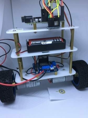
Let get the Structure ready for the self-balancing robot
Put everything together, does not matter what material we use, all we need to do it secure everything together. We can use MDF boards, with some drills in the corner for the standoffs or spacers to make our self-balancing robot. Few holes in between to secure L298N - motor Driver, and UNO board.
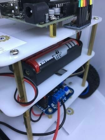
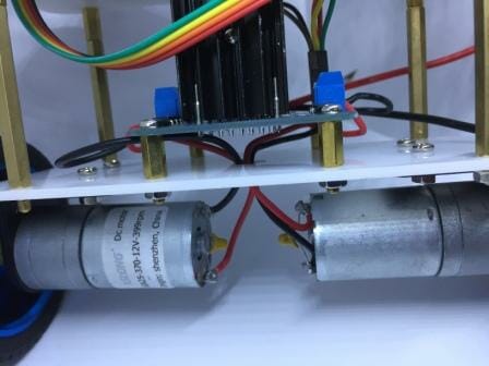
I would recommend putting the motor driver at the bottom close to the motors, then battery finally follower by Arduino UNO and the sensor at the top. You essentially do not have to make 3 layers, 2 should do, however, it is very important to install the MPU-6050 on the top so as go get readings even for a small deflection.
Once you got everything together, it's time to get the electronics working
Here are the connections for the Self Balancing Robot.
Motor Driver ---
- IN1 - Arduino PIN 7
- IN 2- Arduino PIN 6
- IN 3- Arduino PIN 9
- IN 4- Arduino PIN 8
- ENA - Arduino PIN 5
- ENB - Arduino PIN 10
Note - Pin Config might change depending upon the connection of motors to the motor Driver board. If the robot is rotating in axis, try swapping the pins with each other.
MPU6050 -----
- INT - Arduino PIN 2
- SCL - A5 (Serial Clock)
- SDA - A4 (Serial Data)
- GND & VCC
The first step is to calibrate MPU-6050 Sensor
Yes, Calibration is required before we start the calibration we need to make sure the sensor is securely placed on the robot. Once the sensor is secured we need to calibrate the sensor. Download this MPUcalibration code to get the offsets which you will require in your main code.
You will get the offset by Running the Serial Monitor.
Here is the MPU-6050 Offest calibration code
Code Credit - Luis Ródenas
You will require these libraries to run the code :
"I2Cdev.h" - https://github.com/jrowberg/i2cdevlib/blob/master/Arduino/I2Cdev/I2Cdev.h
"MPU6050.h" - https://github.com/jrowberg/i2cdevlib
Please note - All credits to the original developer of the libraries - jrowberg on github, Copyright (c) 2012 Jeff Rowberg
Once you have downloaded the Library, upload the code to Arduino and obtain the offsets. Once you have the offsets, you are good to go ahead into the next step.
Step 2
Understanding the concept is very important before we try to implement the coding for robotics. The idea is to the keep the robot upright by countering the fall and backward fall of the robot by moving the motors forward and backward. The greater the fall is faster the motors should move. The angle of inclination is fed by the sensor and the aim is to maintain the robot verticle.
So now we have a set point maintain all we have to do is move the robot forward and backward to counter the fall. Looks simple but when it comes to implementation it seems almost impossible as the motors will keep moving forward and backward without giving the desired result.
To implement this we have to use something known as PID controller.
What is a PID controller?
Just for the sake of understanding it's an algorithm implementation to maintain a steady state of the system. In our case, the steady state is the setpoint angle and the system is our self-balancing robot. For example a cruise control of a car, we set a speed and the cruise control maintains the desired speed.
To learn more about PID controller I suggest this article - https://www.csimn.com/CSI_pages/PIDforDummies.html
or just google it.
How to implement PID in Arduino?
It seems complicated until we know the libraries to implement PID controller in Arduino which makes the task fairly simple.
Here is the link to PID library. https://github.com/br3ttb/Arduino-PID-Library
PID controller consists of three parts which are most important to understand Kp, Kd and Ki.
- Kp is the proportional gain, this is responsible to counter the error and provide power to the motors to move forward or backward. Kp will act as a multiplier to the error to maintain the desired position. To much Kp will make the robot oscillate, too low Kp will not be able to counter the fall.
- Kd is derivative. It works like a damper to the oscillation. Once you find the best value for Kp and your robot still oscillates, try pushing in some value to this variable. This should control the oscillation of the robot.
- Ki is integral. After getting the right values for Kp and Kd you will notice the robot take a bit of time to come to the desired position, Ki will reduce that time.
Once you have understood this part you are good to go ahead and download this code and try to edit this according to your needs.
Below is the complete code for the Self Balancing Robot
#include <PID_v1.h>
#include <LMotorController.h>
#include "I2Cdev.h"
#include "MPU6050_6Axis_MotionApps20.h"

#if I2CDEV_IMPLEMENTATION == I2CDEV_ARDUINO_WIRE
    #include "Wire.h"
#endif

#define MIN_ABS_SPEED 40

MPU6050 mpu;

// MPU control/status vars
bool dmpReady = false;  // set true if DMP init was successful
uint8_t mpuIntStatus;   // holds actual interrupt status byte from MPU
uint8_t devStatus;      // return status after each device operation (0 = success, !0 = error)
uint16_t packetSize;    // expected DMP packet size (default is 42 bytes)
uint16_t fifoCount;     // count of all bytes currently in FIFO
uint8_t fifoBuffer[64]; // FIFO storage buffer

// orientation/motion vars
Quaternion q;           // [w, x, y, z]         quaternion container
VectorFloat gravity;    // [x, y, z]            gravity vector
float ypr[3];           // [yaw, pitch, roll]   yaw/pitch/roll container and gravity vector

//PID
double originalSetpoint = 181.3;

double setpoint = originalSetpoint;
double movingAngleOffset = 0.1;
double input, output;
int moveState=0; //0 = balance; 1 = back; 2 = forth
double Kp =50;
double Kd = 2.4;
double Ki = 0;
PID pid(&input, &output, &setpoint, Kp, Ki, Kd, DIRECT);

double motorSpeedFactorLeft =0.7;
double motorSpeedFactorRight = 0.8;
//MOTOR CONTROLLER
int ENA = 5;
int IN1 = 6;
int IN2 = 7;
int IN3 = 8;
int IN4 = 9;
int ENB = 10;
LMotorController motorController(ENA, IN1, IN2, ENB, IN3, IN4, motorSpeedFactorLeft, motorSpeedFactorRight);

//timers
long time1Hz = 0;
long time5Hz = 0;

volatile bool mpuInterrupt = false;     // indicates whether MPU interrupt pin has gone high
void dmpDataReady()
{
    mpuInterrupt = true;
}


void setup()
{
    // join I2C bus (I2Cdev library doesn't do this automatically)
    #if I2CDEV_IMPLEMENTATION == I2CDEV_ARDUINO_WIRE
        Wire.begin();
        TWBR = 24; // 400kHz I2C clock (200kHz if CPU is 8MHz)
    #elif I2CDEV_IMPLEMENTATION == I2CDEV_BUILTIN_FASTWIRE
        Fastwire::setup(400, true);
    #endif

    // initialize serial communication
    // (115200 chosen because it is required for Teapot Demo output, but it's
    // really up to you depending on your project)
    Serial.begin(115200);
    while (!Serial); // wait for Leonardo enumeration, others continue immediately

    // initialize device
    Serial.println(F("Initializing I2C devices..."));
    mpu.initialize();

    // verify connection
    Serial.println(F("Testing device connections..."));
    Serial.println(mpu.testConnection() ? F("MPU6050 connection successful") : F("MPU6050 connection failed"));

    // load and configure the DMP
    Serial.println(F("Initializing DMP..."));
    devStatus = mpu.dmpInitialize();

    // supply your own gyro offsets here, scaled for min sensitivity
    mpu.setXGyroOffset(80);
    mpu.setYGyroOffset(-34);
    mpu.setZGyroOffset(8);
    mpu.setZAccelOffset(1569); // 1688 factory default for my test chip

    // make sure it worked (returns 0 if so)
    if (devStatus == 0)
    {
        // turn on the DMP, now that it's ready
        Serial.println(F("Enabling DMP..."));
        mpu.setDMPEnabled(true);

        // enable Arduino interrupt detection
        Serial.println(F("Enabling interrupt detection (Arduino external interrupt 0)..."));
        attachInterrupt(0, dmpDataReady, RISING);
        mpuIntStatus = mpu.getIntStatus();

        // set our DMP Ready flag so the main loop() function knows it's okay to use it
        Serial.println(F("DMP ready! Waiting for first interrupt..."));
        dmpReady = true;

        // get expected DMP packet size for later comparison
        packetSize = mpu.dmpGetFIFOPacketSize();

        //setup PID

        pid.SetMode(AUTOMATIC);
        pid.SetSampleTime(10);
        pid.SetOutputLimits(-255, 255);
    }
    else
    {
        // ERROR!
        // 1 = initial memory load failed
        // 2 = DMP configuration updates failed
        // (if it's going to break, usually the code will be 1)
        Serial.print(F("DMP Initialization failed (code "));
        Serial.print(devStatus);
        Serial.println(F(")"));
    }
}


void loop()
{
    // if programming failed, don't try to do anything
    if (!dmpReady) return;

    // wait for MPU interrupt or extra packet(s) available
    while (!mpuInterrupt && fifoCount < packetSize)
    {
        //no mpu data - performing PID calculations and output to motors

        pid.Compute();
        motorController.move(output, MIN_ABS_SPEED);

    }

    // reset interrupt flag and get INT_STATUS byte
    mpuInterrupt = false;
    mpuIntStatus = mpu.getIntStatus();

    // get current FIFO count
    fifoCount = mpu.getFIFOCount();

    // check for overflow (this should never happen unless our code is too inefficient)
    if ((mpuIntStatus & 0x10) || fifoCount == 1024)
    {
        // reset so we can continue cleanly
        mpu.resetFIFO();
        Serial.println(F("FIFO overflow!"));

    // otherwise, check for DMP data ready interrupt (this should happen frequently)
    }
    else if (mpuIntStatus & 0x02)
    {
        // wait for correct available data length, should be a VERY short wait
        while (fifoCount < packetSize) fifoCount = mpu.getFIFOCount();

        // read a packet from FIFO
        mpu.getFIFOBytes(fifoBuffer, packetSize);

        // track FIFO count here in case there is > 1 packet available
        // (this lets us immediately read more without waiting for an interrupt)
        fifoCount -= packetSize;

        mpu.dmpGetQuaternion(&q, fifoBuffer);
        mpu.dmpGetGravity(&gravity, &q);
        mpu.dmpGetYawPitchRoll(ypr, &q, &gravity);
        #if LOG_INPUT
            Serial.print("ypr\t");
            Serial.print(ypr[0] * 180/M_PI);
            Serial.print("\t");
            Serial.print(ypr[1] * 180/M_PI);
            Serial.print("\t");
            Serial.println(ypr[2] * 180/M_PI);
        #endif
        input = ypr[1] * 180/M_PI + 180;
   }
}
I have found this code on the internet and done some basic editing. Orginal work credit goes to the developer.
Good luck with it and feel free to comment and ask questions.

2 Comments
Great work, Thanks for sharing.
When used this code, it is showing as error compiling for board Arduino Uno.